
The Benefits of Using a Copper Blocker in Mold Base Manufacturing: A Comprehensive Guide
When I started working in the mold base industry over a decade ago, I didn't think much about thermal control. It wasn’t until I saw my first mold cooling failure that I realized just how important thermal management is — and how copper blockers can revolutionize this critical aspect of mold manufacturing.
Since then, I've incorporated copper blockers as part of my standard toolkit when dealing with mold base systems, especially during applications like base cap molding. This article will cover the benefits, implementation methods, and common considerations around the integration of these often-underrated components into modern mold design strategies.
Why Thermal Management Matters
In injection molding, one of my biggest challenges is controlling heat flow. When you're building a mold base system for high production environments, uneven or inefficient thermal regulation leads to poor cycle times and part inconsistencies. Here’s where copper blockers come in. With their exceptional thermal conductivity — up to ten times more efficient than P20 tool steel – integrating them properly into the base framework can offer noticeable differences in part consistency, mold longevity, and cycle efficiency.
- Better heat dissipation
- Reduces hot spots inside the cavity
- Minimizes risk of weld lines during plastic solidification
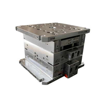
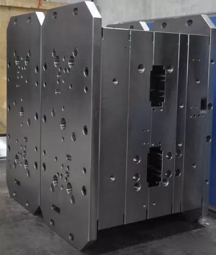
Using Copper Blockers Within Mold Base Construction
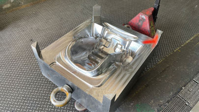
One area that has fascinated me over the years is how copper blockers work within modular mold frameworks. They typically sit between ejector pins and core inserts — strategically placed where maximum temperature fluctuations might occur. For molds used for complex geometries like automotive parts (especially using techniques related to Base Cap Molding), this makes the process much smoother in terms of maintaining dimensional tolerances and surface integrity of finished goods.
| Material | Coefficient of Thermal Conductivity (BTU/ft/hr/°F) | Vickers Hardness (HV1) |
|---|---|---|
| Copper Alloy – C18200 | 74.3 | 130 |
| P20 Tool Steel | 7.9–12.6 | 350 |
| Dynabond B0800E | 29.8 | 240 |
Note: While copper is softer than traditional tool steels, proper design and positioning ensure that they won't interfere with structural integrity of your mold base structure — and they still maintain enough toughness to function under pressure. My advice? Design support walls around the blocker area, or consider bonding agents to protect the softer sections against wear.
The Practical Integration Process
This brings me back to a project from a few months ago where my task involved revamping an older mold setup for improved output. One thing became evident almost immediately — the old thermal distribution system was inadequate.
- Determine areas prone to localized overheating
- Calculate ideal surface contact needed with cooling circuits
- Carefully machine slots within the base plate to accommodate blockers
How To Cut Copper Plate – My Proven Technique
If you're new to working with conductive materials in base cap molding, machining copper isn't straightforward due to its tendency to gum up on cutting surfaces. I've wasted plenty of time here, trust me.
below breaks down what worked for me — based on trial, frustration, and eventual satisfaction. Don't underestimate the importance of coolant coverage while machining — flood systems are generally preferred over mist.
| Tool Type | RPM Setting | Feed Rate | Coolant Used |
|---|---|---|---|
| T-Carboloy End Mill - ½" | 5000 rpm | 17 ipm | Semi-Synthetic Water Soluble |
| HSS Drill Bit | 2500 rpm | 10 ipm | Mineral Based Straight Oil |
I’ve learned over time it helps significantly to pre-bake any moisture-sensitive stock before actual processing — particularly relevant for humid climate zones, such as my current shop space which sees summer humidity spikes regularly. This step improves overall stability post-finishing and reduces distortion issues later during mold operation cycles. So take that extra hour if needed before proceeding.
Copper Blockers and Cooling Efficiency – The Science Inside My Workflow
During my last two large-scale operations using copper-based thermal blockers — one focusing primarily on precision electronics packaging, and another on cosmetic lid design — we recorded an estimated reduction of **8% to 12%** in overall cooling phases per injection cycle.
If your copper blocker placements are calculated properly, you could save hours of runtime weekly, translating to higher profit margins and reduced tool fatigue.
Of course, every mold setup differs in complexity and purpose, so there’s a fine line in maximizing return versus over-designing features unnecessary for specific mold profiles.
The Cost Implication – Is It Worth Implementing?
Let's address cost head on: incorporating custom-machined thermal blocks does add to initial manufacturing costs. On smaller molds ($5k-$10k budget), plan to set aside an additional $800-$1500 depending on alloy selection and number of required insert points across the entire mold base. That may seem significant upfront but believe me, over long runs the ROI speaks for itself.
Maintenance Considerations
An important factor I neglected to emphasize during earlier phases of learning this process — corrosion resistance in copper — came at an expensive rate one season. Always verify with your alloy specifications before starting work on your final production mold build. Oxidation and water-line erosion happen fast in moist environments if no plating treatments (nickel, chromate) have been done prior.