
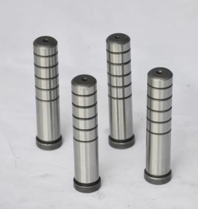
The Importance of Selecting the Right Mold Base Steel
I can tell you that selecting the right mold base tool steel plays a crucial role in both the life expectancy and efficiency of your production system. When it comes to plastic molding operations, whether for medical device parts or large industrial components, your tooling must handle wear and maintain tight tolerances without constant maintenance. The key factors I evaluate when considering which steel alloy suits best includes hardness levels (usually between HRC 28 - 52), heat conductivity, surface finish stability and ease of machining. It's important not to assume all high-end alloys are ideal — sometimes medium carbon steels like S45C will serve your specific applications better depending on mold size, run quantities, and material types used.
Metal Properties That Influence Mold Performance
- Wear Resistance — essential for preventing surface erosion in moving components over extended cycles
- Tenacity — avoid brittle fractures especially in molds exposed to uneven pressures during operation hours
- Dimensional Stability — critical post tempering treatments to avoid warpage from temperature variations
| Tool Grade Name | Benchmark Hardness | Main Additives (Chemistry) | Cool Flow Characteristics |
|---|---|---|---|
| LKH150 / M2 Class Steel | HCR 60–65 | V,Mn,Wo content high | Poor weld but good polishing trait |
| S34CrMo Alloy Steel | RHC around 47 after treatment | Incorporate Chromium Molyb | Air hardening suitable option |
| Nak 55 (Plastic Grade Type) | HRR approx. 52 | Additions of Nickel + Niobium | GREAT EDM capability & polishability |
| P-xx Tool Grades (Low Carbon Types) | Softened under HHR 30 initially | Low C% with Sulphur additives optional | Better formability but limited longevity |
Understanding Base Molding Trim Components And Compatibility Concerns
We often see trim issues arising specifically due to mis-mating between the mold plates main support frame vs smaller detail areas like side cores or undercut sections. The term 'base molding trim’ generally refers to secondary structural elements bolted into the primary tool frame to shape certain profile edges and intricate cutouts needed by customer specs. What people may not know is that those inserts should ideally come from matching material families to eliminate stress cracking caused from mismatched thermal expansions.
Common Mistakes in Trim Material Selection Process
- Select materials purely based upon visual texture needs ignoring internal stress points
- Assuming copper alloy trims (such as PDS 5) are compatible with standard quenched mold plates without isolator layers in between them
- Underestimate impact loads in ejection zone trims which leads rapid failure unless hardened correctly first
- Making unnecessary design compromises due to outdated misconceptions about older alloy performances
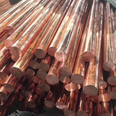
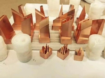
Copper Block Texture Applications – When Is Thermal Responsiveness Key?
If we dive a little deeper here... there comes situations where mold texture requires specialized metal blends beyond common die tool steel solutions. The most frequent one I encounter deals with copper blocks integrated to allow faster heating / cooling transfer across textured surfaces — this becomes particularly useful when trying achieve a leather look or simulated stone effect over larger injection shot dimensions without causing defects from trapped steam condensations. This brings in keyword: 'copper block texture' optimization strategy.
Note: Copper-based insert materials like Glidcop or beryllium copper aren't direct replacements for structural core components — they act more like localized pressure dissapers and heat sink modules.Considerations For Integrating Conductive Materials Into Mold Base Plate Layout
Achieving a successful installation isn’t merely slotting a copper part next to steel; its integration demands precise boundary conditioning including:
- Limited depth contact zones — prevents cold spot generation from sharp transitions.
- Treating bonding faces for chemical adhesives to ensure no moisture buildup gaps occur at junction lines.
- Balancing cavity spacing near texture region for avoiding thermal differential stresses that might compromise final part surface clarity.
| Metal Type | K value W/m-K | Economic Impact (per cubic mm cost basis USD $1 = avg std plate rate.) |
|---|---|---|
| DIN C45 Tool Carbon Plates | ~ 45 W/(m·K) | $1.00 |
| H13 Pre-treated Chrome Moly Alloys | around ~28.9 | About $1.50 per cm cube roughly |
| Copelloy CX-1 (Modified CuAl) | > 160+ | Higher upfront — possibly triple or more |
Manufacturers Guide To Evaluating Your Options
What usually happens out in manufacturing floor space is many people rush the decision making process — jumping into ordering whatever supplier has shortest lead time at cheapest pricing without considering how each product’s composition actually meets functional demands down the road. As someone who’s been evaluating various plate forms — cast blocks, vacuum arc melted slab versions or additive fabricated shapes recently too, let me give a realistic assessment criteria based upon real-life experience in production trials over recent seasons. Let's explore four core considerations before finalizing your plate purchase decision.
Critical Decision Factors For Optimal Material Match Making
- Budget Forecast Alignment: Will initial capital layout be compensated by extended operational uptime versus cheaper options needing higher turnover rates.
- Process Integration Testing Time Allowance: Does schedule allow for conducting pre-trials for complex combinations requiring special prep (nitrocarburizing procedures maybe?)
- Lifespan Expectancy Under Project Loads: Use historical data of same application elsewhere to guide choices. Don't go strictly by manufacturer datasheets.
- Harder grades often mean trade-offs in brittleness under impact loads unless specially modified chemistries added in advanced melting phase of plate production,
- You really don’t want mismatch your copper trim pieces unless thermal insulative buffer layers present between other metallic structures to stop thermal shocking failures.
- That texture demands must drive certain decisions, particularly when integrating ‘copper block texture zones.’ So what now? Well here’s practical plan you can implement within next two weeks: Road Map For Implementation Success Checklist Item No. 1 - Reach out local metallurgists and arrange for free sample packs so testing available alloys becomes possible. Step Two - Run simulation using finite element analysis software that helps simulate fatigue risks under variable operating conditions likely encountered in field deployment of these components. Lastly — document your findings along trial path even if things don’t perform up expectations initially — building institutional knowledge over material performance pays back tenfold during future purchasing negotiations.
Pricing Structures Versus Mold Base Longevity
From years working alongside engineering shops dealing with high-volume mold runs — one pattern clearly arises regarding tool selection: short-term expense shouldn't dominate entire equation. Sometimes spending 20–30% additional upfront results in halved service interventions every few hundred thousand shots — ultimately cutting lifetime expenses dramatically despite pricier starting point. Let's highlight what differentiates “cheap" from smart buy approach below in comparison terms.| Mold Component Role Complexity Rating Low to High | Easiest Production Setup Conditions Needed | Estimated Initial Spend Range | Projected Lifespan Shots Estimate Approximations |
|---|---|---|---|
| Low Complexity | Simple CNC routing only minimal post work | $7000-$15k average bracket | >12500 cycle life potential assuming proper storage between jobs |
| Midrange Detail Inlays & Slides Allowed | Wire cut and bench polishing stages involved but not full assembly pre-hardening required upfront | $30k-$48k bracket dependent upon number of features inserted and precision demanded | Expected lifespan stretching towards 400k cycles if maintained regularly every few month interval period. |
Concluding Thoughts and Practical Next Steps Toward Optimization
Ultimately what matters the most when purchasing a new set-up tool steel plate series isn’t following a fixed formula or industry default recommendation — but rather looking closely how the material behaves in tandem with current equipment profiles plus understanding long game usage projections for mold replacement patterns. By now I hope some key takeaways stuck such as knowing: