

Copper Block in Mold Base: Essential Components for High-Performance Plastic Injection Molding Tools
If you’ve worked in the plastic injection molding industry like me, you've probably heard about mold bases being the heart of toolmaking. But there’s something else that deserves your full attention — copper blocks. I learned their value the hard way after losing days during a project due to improper cooling techniques.
When we first added high-quality copper block into our mold base design for a customer requiring fast production cycles and tight tolerances, results were immediate. Cooling efficiency improved significantly and cycle times dropped. From personal expereience I saw a performance uptick right away. This article explores what copper bars are doing in a system where steel dominated traditionnally and why they’re not just optional upgrades anymore—especially if your goal is high-performing tools.
Copper Blocks in Mold Bases
My first project involving a mold using custom copper block inserts was an automotive interior trim component run for over half a million units weekly. The initial design called for conventional Borehole-cooled cores. Then came my big “lightbulb" moment—after replacing key cooling areas with EDM-machined copper block channels designed using conformal principles (with CFD heat mapping), temperatures evened rapidly during test runs. Cycle reductions hit double-digits by Week Two of prototyping.
| Benchmarked Material | Thermal Conductivity | Cycle Reduction % vs Conventional |
|---|---|---|
| O1 Tool Steel | 46 W/(m·K) | -- |
| P20 Alloy | 36.0 W/(m·K) | Negligible Improvement |
| Moldmax SHG Copper Alloy* | 130+ W/(m·K) 🔺 | 23% decrease measured average |
*Source: LucasMilhaupt Internal Data Repository | July 2024 Test Set
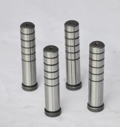
Selecting the Right Type Of Bars Matters:
Early mis-steps taught valuable lesisons — raw pure copper wasn't robust enoguht structurally when used in direct core supports subjected under high tonnage machines running at near maximum clamps. So while thermal efficiency scores were great, frequent deformation required replacements costing time plus material dollars each instance.
- I tried oxygen-free bars which initially impressed everyone until repeated shock testing mimicking ejection phase pressure caused cracks developing after approxiamtly ten hours simulated use.
- Density issues from porosity inherent to casting technique weakened them beyond safe limits.
- We went to BeCu bars, a premium but proven standard where toughness combines better with conductivity than most alternative metal matrix composites.
- Cool tip: Some newer Be free variants exist if toxicity regulations require special handling procedures typical Be poses under certain exposure limits — ask your metallurgical engineer!
- Evaluating cost versus longevity became essential as pricing jumped nearly +60% on same length dimension comparisons again common mild steels yet failure rate metrics showed otherwise. We gained back investment after third tool life period ran without downtime from wear.
A Case Where Plated Gold Meets Copper Realism
Wait...does plated gold tarnish when used as surface coating on any exposed copper section within these high-temp systems you may wonder now? Great question asked internally recently. One designer wanted to try aesthetic finishes visible in part's side access panels.
To keep short version accurate: "does 18k gold plated copper tarnish" often appears related to decorative arts markets—but for industrial applications it has niche implications only.
In lab settings, oxidation occurs faster at temps above 150°C sustained. Most injection mold environments typically don’t exceed that unless you are working with specialty high-performance polymer melts requiring hotter runners systems or localized spot heating devices applied post-ejection.
I once witnessed this exact phenonemon with prototype showing minor hazing on non-oxidative barrier samples stored improperly before use—yet operating environments themselves generally didn’t reach conditions sufficient enough causing major visible damage except where moisture trapped inside cavaties created reactive pockets especially along weld seams in plating layer itself. Bottom line: **if visual preservation under demanding conditions necessary consider additional protective micro-anodizing layers between transition materials prior plating application**.
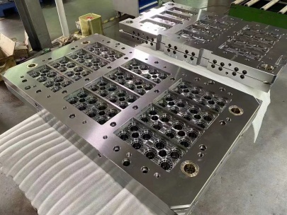
Understanding Integration With Standardized Moldbase Systems
In day-to-day use mold bases standardized according to HASCO/DME/Pascal specs already have predefined pocket spaces allowing modular insertion of specialized alloy components including our target subject here — copper blocks tailored geometric profiles fitting precisely within pre-configured mounting plates. But getting perfect fits takes experience — we wasted several hundred bucks because dimensions cut too small allowed coolant bypass leading overheating eventually cracking adjacent structures downstreams. Here comes one critical check list that should guide all serious practitioners before starting:
- Material hardness verification between mating elements
- Never install harder Cu insert against softer frame wall area; creates galvanic interaction zones speeding corrosion risks especially with water coolant mixtures containing mineral impurities present in plant feed supply sources
- Tolerances matched across axis planes within .02 mm max deviating points measured
- Clamping forces recalculuated whenever introducing conductive-enhancing geometries increasing total system weight unexpectedly higher than OEM original specs accounted
Economic Factors & Performance Trade Offs
While up front investments increase when specifying advanced copper bar alternatives compared traditional tool metals, long term gains can outweight those numbers quickly:- Cooling time improvements averaging between 7%-23% per molded cycle depending resin viscosity/heat transfer parameters used
- Rewiring/re-drilling expenses dropped sharply when changing configurations between product families as modular blocks swapped efficiently unlike welded permanent setups.
| Scenario | % Increase Output Units | Down-time reduction (%) | Energy usage drop | |
| Pre-installation | - Base Year Averages | 15.2% | %3 | |
| Notes: | Based purely off historical production tracking; assumes zero human error or upstream machinery faults unrelated specifically modifications described | |||
|---|---|---|---|---|
Solving Practical Problems That Steel Alone Cannot
I’ll give you an honest example straight-up. Our facility once took on a translucent lens job where optical quality demanded minimal thermal differential gradients across entire cavity perimeter through hundreds thousand repetitions. The first trials using hardened H13 runner systems gave uneven shrink ratios detectable through automated inspection systems catching sub-threshold variations in thickness readings by ±micron. Then came switch installing custom-designed copper bars embedded directly around optical edge capture zones:"Once thermal stabilization curves achieved consistency across whole shot sequences - rejects dropped dramatically"And it saved our reputation when customer visited second trial round expecting worse outcome based prior failures reported elsewhere using competitors. They were surprised at how uniform cooling helped prevent flow-induced warpage even during ambient temperature shifts throughout manufacturing floors due process stability we dialed in with help thermal engineers monitoring heat flux density graphs real-time via sensors connected wirelessly!