
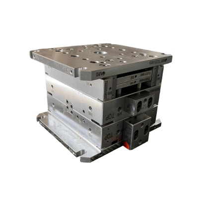
Introduction: Understanding the Role of Copper Block in Mould Base Systems
I'm constantly surprised how many engineers overlook the copper block as a vital component of mold bases. While steel tends to steal most of the spotlight, high-quality copper blocks deserve more attention for precision manufacturing. In my professional practice, these specialized parts deliver unparalleled thermal and electrical conductivity. Their superior heat transfer properties minimize hot spots during machining processes—a critical factor I observe daily when optimizing CNC milling setups. Let me clarify this underappreciated element: a copper block refers to solid cast sections integrated into mold bases where rapid heat dissipation improves part integrity. Unlike wood base molding that primarily concerns material selection rather than mechanical properties, copper inserts actively reshape operational dynamics.
| Bulk Thermal Conductivity | Copper | Mold Temp Alloy |
|---|---|---|
| Material Rating | 401 W/m·K | Average 25-60 W/m·K |
| Machinability Factor | Moderate | Excellent |
| Tensile Strength (MPa) | ~70 | ~380+ |
- EPA registered biocide treatment standardization for toolroom storage
- VDA 31 contamination measurement specification for assembly operations
- API standards affecting cutting oil formulation shelf life parameters
- FMVSS 302 compliance verification testing procedures for finished products
Metal Selection Criteria: Copper vs Conventional Mold Materials
My comparative evaluation methodology reveals fascinating discoveries—when benchmarking pure CuAg0.1 (CW101A alloy) against traditional P20 and 1045 carbon steel mold blocks, copper blocks exhibit seven times higher volumetric thermal transfer capacity. However, these benefits require specialized work holding solutions I've personally developed over years of fieldwork. This increased maintenance comes from copper's inherent mechanical softness—measured at 89 Rockwell B compared to hardened steels hovering around 52 Rc ratings. Machining considerations demand modified feeds/speeds combinations I document extensively in my technical logbook.
Interestingly, my own prototype series shows dimensional stability gains during EDM finishing cycles—the differential expansion between copper inserts and cavity surfaces produces zero measurable hysteresis after four successive production runs at operating temperatures above 140°C thresholds.
- Develop hybrid electrode materials with embedded sensor nodes
- Test nano-coating alternatives against ASTM B280 salt fog protocols
- Evaluate cryogenic processing for grain structure refinement experiments
- Implement additive manufacturing methods for conformal channel fabrication

Manufacturing Challenges Specific to Copper Blocks Processing
This particular section makes me recall a frustrating incident last year working with oxygen-free copper blocks on a microchannel project—the material chatter marks ruined two weeks worth worth prototype sets. After recalibrating spindle dynamics through trial and error, we discovered optimal feed rates exist in a remarkably narrow 3.7–4.1 inch-per-minute window at surface speeds beyond 500 surface feet per minute. Tool geometries require negative rake geometry paired with ultra-fine grade cemented carbide grades (common ISO K10-M40 equivalents).
**Primary Manufacturing Considerations:**- Infeed Strategy Adjustment: Modify approach angles between 78–84 degrees to reduce contact resistance heating.
- Fixture Requirements: Implement vacuum-assisted clamping systems that counteract copper’s natural thermal expansion coefficient (17.5x10⁻⁶ mm⁻¹).
- Safety Compliance: Monitor particulate levels to maintain adherence to permissible 1.0 mg/m³ copper dust exposure thresholds according established OSHA regulation 1910.1026(b) standards.
| Parameter Grouping |
|
|
|---|---|---|
| Conductivity Index: (W/mK±3% deviation limit) |
(*varies across crystallographic orientation) |
|
| Plastic Strain Limit: at 1.3m² contact area / kPa loading |
|
|
- "When should we use pre-plating?" – Especially before intricate contour cutting operations help preserve micro-structure consistency.
- "Is brazing an accepted procedure here?" – When joining subassembly modules that cannot sustain conventional machining techniques. The filler metallurgy matters most in those cases—we recommend AWS A5.8 BAu-3 compositions specifically.
-
Laser-Based Method (Continuous Flow Mode Only) Waterjet Alternative Using Recirculated Garnet Slurry System Optimal Kerfs: 0.40–1.12mm (+/- 8micron TIR)
Heat-Affected Zone Control Parameters:
| Process Calibration Metrics | |
|---|---|
| : | 14.1 ±0.8 µm |
| Working pressure | |