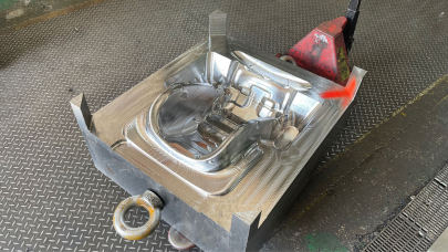
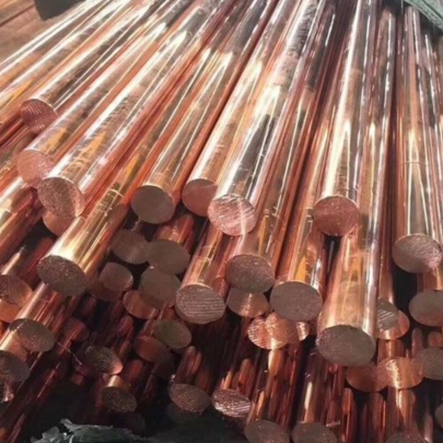
The Role of Copper Blocks in Enhancing Mold Base Performance for Precision Manufacturing
I’ve spent years navigating the ins and outs of mold base systems, and nothing’s more frustrating than dealing with poor heat transfer. When you're trying to maintain tight tolerances—whether we’re talking about A2 steel mold plates or a complex multi-impression core—you need performance that’s both repeatable and reliable. In high-stakes precision manufacturing, one component has emerged as the unsung hero of this stability: copper blocks.
Why Mold Bases Need More Than Standard Materials
If you've been around mold bases (especially ones built with conventional materials like 45 Steel), then you know how easy it is to run into warping or cooling inconsistencies. I've seen it happen on some of my toughest runs, particularly during extended production cycles where uneven heat becomes an uninvited third wheel.
- Overheating causes premature wear.
- Metal distortion leads to rework costs.
- Inadequate cooling translates to longer cycles.
A typical mold base can't compensate fast enough if internal channels aren't perfectly placed or if thermal resistance within mold inserts becomes too significant. Here's the kicker: switching over part or all of your mold insert area with copper components can dramatically improve performance. That’s assuming, of course, you understand the right alloy choice—and not all conductivities are created equally.
| Mold Material | Thermal Conductivity (W/m·K) |
Hardness (HRC) | Typical Application |
|---|---|---|---|
| A2 Steel | 38–46 W/m·K | 50–60 HRC | Mold bases with moderate cavity retention |
| D2 Steel | 32–38 W/m·K | 55–60 HRC | Tooling where wear resistance matters more |
| Pure Copper Block | 398–401 W/m·K | 55 HV max (as annealed) | Cooling enhancement inserts near injection gate zones |
| H62 Brass | 110 W/m·K approx | 65–70 HRB | Sometimes as standoff supports in mold stack assemblies |
Pure Copper Blocks Aren't Just Heat Conductors; They’re Predictors Too
Back when I was still skeptical myself, a veteran toolroom supervisor once said: “A pure copper block isn't just a piece that moves heat faster — it's the element you lean into for thermal predictability." And frankly, I couldn’t agree more. If you’re chasing consistency shot after shot, integrating even just two or three strategically placed copper inserts into critical zones, especially where runners come in hot, makes an enormous difference.
- Better conductivity means less dwell time.
- Rapid heat evacuation prevents burn-through on surface skins.
- Likely to reduce flash at gate areas when combined with A2-based mold plates.

If you haven't yet, start analyzing thermography data alongside your cavity pressure logs next month. Odds are, you'll catch something missed by sensors alone. And trust me—I saw that exact gap cost my shop thousands before we added a couple embedded C1100 copper elements. Once calibrated for fit and shrink-fit tolerances against hardened cores… wow, the improvements in uniform ejection patterns were night-and-day.
Tailoring Your Use of Mold Materials—A Balanced Perspective Between Steel and Conductive Inserts
This next part may sound obvious to veterans, but it needs stating clearly: Not every application deserves pure copper blocks slapped everywhere. Let's get specific:
- I've had shops overdo copper placement in ejector sideplates without considering clamping alignment forces. Spoiler alert: the material deforms way sooner compared to a well-tempered 3CrW8V plate.
- I learned that stacking soft conductors like Cu-Ag alongside harder substrates such as AISI A2 needs more care than a casual engineer expects — especially regarding interstitial spacing.
The key? Integrate pure copper block solutions only where they make physical sense in real applications. No theory-only placements—only those validated under pressure cycling simulations.
Bridging Theory to Reality in High-Demand Production Environments
Theoretical studies look solid—but reality is messier. One of the hardest things I ever did early in my plastics molding days was convince leadership that switching our PDS systems wasn’t optional. It came down to data: cycle analysis, defect mapping against cooling profiles, and—believe it or not—the number of ejected bad shots per thousand-run sequences versus mold design types.
Quick Wins Observed:- We used CAD thermal simulation software ahead of builds.
- Ran dual sets in testing—one control build using all-A2, another enhanced using two custom milled pure copper segments behind nozzle contact point.
- The result? Significant improvement across 4 out of 5 tested geometries.
- Don't just rely on standard P-steel anymore without comparing alternatives in your niche field.
- Keep a small test batch of your existing tool builds and compare them against prototypes using optimized mold base layouts that feature integrated purer copper alloys such as C10300 or OFHC copper—especially where gate proximity heating occurs.
Now here's something else you should know. There are also cases—not frequent—but documented where companies have actually started retrofitting legacy mold setups mid-life, and achieved noticeable life cycle extension gains through partial use of copper blocks where heat entrapment previously limited productivity levels to unsustainable states prior to intervention efforts kicking off fully formal programs.
Frequently Asked Myths Surrounding Thermal Management with Pure Copper Inserts
| Type | Advantages Over Copperless Designs |
|---|---|
| Copper-Enhanced Core Assembly | ✔ Faster cycle times due to lower equilibrium temperature. | ײ) Higher initial procurement vs standard setup. +<br/> Easier maintenance via reduced carbon buildup during long-term operations. |
| Mild-Steel Base Plate | - Slow Cooling.*Inconsistent Much lower conductivity; no edge gain from adding copper unless core proximity exists. |
| No | Myth Type | Reality Check From Real Experience |
1 |
“Copper wears too fast so its durability can't handle daily operation" | → True, if pressed into heavy impact positions (like parting surfaces). Otherwise, it can easily last for >28K cycles when used properly for back-inserts adjacent runner sections. Some tools have shown zero degradation at touchpoint interface until after nearly 15-week active running sessions with aggressive lubrication management plans in parallel. |
How Should Your Company Start Applying These Findings Today?
Here’s a realistic checklist based on what my past experiences have shaped:- Review your recent reject percentages by product segment, specifically looking at geometry-driven distortions possibly due to heat buildup in specific zones (often corners or thick walls). This is usually where pure copper blocks earn their value quickest in new tool projects.
- Run a simple thermal profile comparison between your current toolset and simulated alternatives incorporating higher-conductive materials, even using open-source FEM analysis platforms like FreeCAD THERMAL module or basic SolidWorks Flow.


