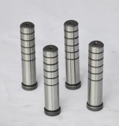
Does copper effectively block electromagnetic fields, and what implications does that have for shielding in mold base applications during the complex process of injection molding? I've been digging deep into electromagnetic compatibility issues lately, especially after noticing unusual variances in component quality near certain tool setups in one high-precision production run. That nagging curiosity led me down a rabbit hole connecting physics principles with industrial manufacturing requirements.
Let me start with my fundamental realization - while copper's electrical conductivity makes it excellent shielding material, there are critical limitations. EMF blocking isn't binary but depends on field type (electric vs magnetic vs RF), source frequency, required attenuation level, and crucially - application-specific constraints including thermal management needs in hot runner molds. I still vividly remember testing prototype copper shields around inductive proximity sensors, where performance paradoxically worsened above 10 MHz frequencies without complementary design changes.
Key Copper Performance Factors
| Factor | Copper Properties | Influence Level |
|---|---|---|
| Eddy Current Shielding Effectiveness | 98%+ @ 60Hz for 0.5mm thickness | 🢙 |
| Microwave Attenuation | ~37dB for standard sheet | 🢙🢙 |
| Skin Effect Threshold | Begins @ ~1MHz | 🢙 |
| Tensile Strength Retention | <90MPa when >1.2mm | 🢙🢙 |
- My first revelation - Copper lacks intrinsic magnetostatic screening capability compared to alloys like A4 Steel that offer 6x magnetic permeability retention
- Melting point constraints matter - When considering cooling passages proximity, pure Cu risks degradation beyond critical creep thresholds above 200°C operational limits
- A2 tool steels provide dimensional stability maintenance within +/- 0.001" through multiple tempering cycles
- Pretty sure I'm not alone who's struggled with EMI reflections bouncing across uneven shield surface finish roughness causing micro-resonances
- You know what's fascinating about platable materials behavior? The way copper develops natural oxided layers over months dramatically changes skin impedance values at microwave bands
If there's one takeawawy from two decades watching plastics flow behaviors... Mold steel selections must consider electromagnetic dynamics as much mechanical wear metrics. But let me clarify why...
The Unavoidable Compromise in Thermal-Electric Shielding Design
This came up during recent cavity pressure sensor integration attempts using copper-shrouded connectors. While signal-to-noise ratio improvement initially seemed promising below AM broadcast range (~5 dB enhancement), higher-frequency transients caused by servo drive commutations remained unaffected until adding carbon-fiber reinforced elastomer seams between metal interfaces.
Copper Application Trade-offs Compared:
- ✔ Superior thermal transfer dissipation vs A2
- No inherent ferromagnetic damping characteristics
- Machining costs frequently double per cubic inch processed versus typical pre-hard tool steel grades
- Surface oxidation creates variable RF performance curves post-machining unless sealed properly

Facts Often Overlooked About Mold Base Materials Interactions
* Remember this important distinction regarding grounding strategies* Don't fall into assuming continuous contact path always enhances ESD protection capabilities
* Beware that most dielectric pastes alter expected field distributions in sub-MHz spectrum
- Volumetric Skin Depth(&dgr;= sqrt(ρ/(π·μ0f)) relation
- Describes how alternating current penetrates conducting materials decreasing to 37% bulk intensity every &dgr; distance traveled - critical factor determining necessary shield wall thickness in mold components exposed >10MHz environments
Distinguishing Critical Variables in Electromagnetic Environment Exposure
While reviewing specifications for custom copper waterblock solutions, my biggest headache involved reconciling coolant path integrity under vibration-induced fatigue versus required isolation effectiveness from nearby heating bands operating in 20-50 KHz induction ranges. Surprisingly few resources connect fluid dynamics considerations with electromagnetic compliance simultaneously for molded optics tooling scenarios:| Type of Coupling | Shield Performance Requirements | |
|---|---|---|
| Radiated Immunity (GHz Range) | Conducted Susceptibility (<1kHz) Magnitude | |
| Capacitive Coupling | Moderate (18Ghz: ~4dB insertion loss) | Critical - Requires complete circuit bond planes |
| Mutual Inductance Risks | Severe degradation observed past 0.7T flux density levels | Copper ineffective here without lamination approaches comparable A2 laminates stacking sequences |
Now here’s what really kept me awake nights – the interaction between moving mold halves' positional tolerancing during ejection phases interacting with static fields from nearby robotic welding cells! We found out the hard way copper-backed slides showed pronounced chatter artifacts under magnetic pull forces when clamped mold stackup geometries weren't aligned symmetrically around major field vectors.
Critical Take-Aways for Practical Implementation in Production Floor Scenarios
- Always measure actual incident field distribution across machine before implementing any shielding strategy — assumptions made from schematic-level analysis can mislead badly.
- Maintain minimum of 0.125" setback distance between magnetic actuators/sensors centers versus conductive barriers containing ferrous/nonferrous combinations to avoid distortion lobing effects
- Laminating multiple material types often proves far more economical than solid pure-conductivity elements – combining aluminum extruded forms backed w/ stamped copper foil layers works well in structural parts moldings requiring modest attenuation.
- Verify that all cable entries pass through designated zones that maintain proper equipotential references with grounded steel support structures minimizing induced differential voltage rings around workspaces.
Pro tip discovered while battling warpages – Integrating thin copper films just inside ejector sleeve channels provides measurable localized EM suppression benefit without compromising heat removal or increasing maintenance complexity too severely!


