
The Benefits of Using High-Quality Mold Bases with Copper Blocks for Efficient Manufacturing
Index
- Introduction to Mold Base Manufacturing & Thermal Performance
- Why Copper Blocks Make a Difference in Efficiency
- Types and Uses of Copper Printing Blocks
- The Importance of Quality Mold Base Design for Manufacturing Excellence
- Exploring Cooling Solutions – Are Copper CPU Water Blocks Worth the Hype?
- How to Choose the Right Combination of Mold Bases and Copper Blocks for Optimal Production
- Technical Breakdown: How are These Components Actually Used Together in Industry Applications?
- Key Points Summary: Why Investing in Mold Bases with Embedded Copper Is a Strategic Advantage
#1: Introduction – The Growing Role of Heat Management in Tooling Precision
If I’ve worked through enough metal fabrication and mold making environments like yours — then trust, we both understand how even minor variables can shift production timelines, costs, and final outcomes. In industries such as plastic injection, precision casting or die-cut toolmaking; it’s often said — "It all starts with your base". That refers — more directly than one would assume — not just to structural integrity but to heat dissipation properties tied to materials selection.
| Manufacturing Type | Heat Generation Per Cycle (approx.) | Degree Sensitivity Needed | Ideal Block Material Suggestion |
|---|---|---|---|
| Molding Injection (PVC/PP/etc) | 220°C+ | +/-5% | Copper Blocks + Steel Support Base |
| Die Cast Tools (Aluminum) | 380+°C (Molt Temp Zone) | <-15%, but sensitive per alloy spec | Mixed conductivity inserts only on cooling cores |
- Efficiency losses due to thermal delays add between .2-.7 seconds per injection stroke in high-speed cycles.
- Material deformation from repeated stress points often initiates from poorly cooled block zones.
- Misalignment due to temperature-based swelling is commonly seen in substandard builds.
I started looking closer at what exactly made one mold base perform so differently against another after years of seeing subtle quality shifts. Eventually, that curiosity brought me directly to where copper enters the frame — not just as raw components — but deeply-integrated inside mold support blocks for active cooling and heat redirection purposes.High-quality mold bases using embedded copper technology were turning into standard practices for advanced shops by around late ‘16 to early ‘19 period across US manufacturers who could justify the investment.
#2: The Core Benefit Behind Copper Blocks vs. Standard Options

Solidified mold manufacturing techniques have always centered around stability — steel and other durable metals form primary structures while additives improve resistance, surface hardness, wear characteristics etc. But there remains an ongoing struggle over temperature consistency, particularly when you're cycling thousands of repetitions with molten resins and complex geometries being shaped. Let's cut the BS here — most folks won't realize their mold’s performance ceiling until you've integrated actual heat-dispersal control points using **copper printing blocks.**
- They reduce cooling cycle times up to 22% compared to conventional core designs without internal heat transfer features;
- Cutting down part warps during solidification because the mold cools uniformly across the cavity;
- The thermal conductance property outperforms any standard aluminum alloy used today.

Commonly Misled Claims
Let’s get this right — **not every 'copper-infused' mold insert will perform equal benefits.** I've run into sales guys promising thermal conductivity boosts without specifying how those pieces interact thermodynamicaly within surrounding material matrices. If a “**copper CPU water block**" analogy seems relevant somewhere in the explanation, then perhaps they're borrowing ideas from overclocker tech rather than industrial standards.✔ Real-world applications rely more closely on geometric distribution principles and material interphase boundaries than simply placing a hot-metal slug where heat builds. It’s physics plus engineering applied together smartly.
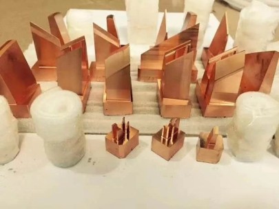
#3: Understanding Variants of Copper Printing Blocks: From Simple Inserts to Microchannel Designs
I’ve found in multiple mold-making houses, copper block setups fall roughly into 3 distinct tiers in practice:
- In-line copper bars inserted near ejector sleeve holes for targeted cooling zones;
- Full cavity-backed sheets with internal channels for laminated-style cooling;
- "Bendable printed" blocks designed in CNC-laminar layers forming intricate coolant flow chambers via EDM milling patterns (often called conformal blocks).
Type Metal Form Use Cases i. Bar-style inserts Cuttable bar stock with pre-formed borelines drilled cross sectionally. Coolant ports near ejection pins where overheating issues emerge first under normal conditions. ii. Flat sheet variants Square slab copper sheets with serpedin milled channel patterns Support for backside cooling across long flat surfaces prone towards thermal sagging after hours of cycling iii. Print-like lamination layers Built via thin-layer sintering, similar 3d print technique (metal layer sinter + press forging) Nested mold forms requiring complex geometry matching cavity curves — popular for medical or microchip housing cases needing zero tolerance variance across molded units. These are often referred to also as 'Conformally cooled’ copper printing blocks. 
The biggest problem isn’t picking any variant blindly; rather the decision needs analysis backed simulation runs. Which ones actually match my project's geometry profile — and what's the real impact if some regions retain residual heat beyond threshold specs? This comes back again to why investing upfront into mold bases engineered specifically with these integrated solutions pays off downstream despite higher initial costs.
#4 The Importance of High-end Mold Base Selection: A Critical Starting Point Before Anything Else
This isn’t a story I like to repeat publicly but... One time I took delivery of brand new mold tools thinking full well they’d pass QA tests. Nope — turned out a critical alignment dimension slipped by inspection. What was worse: retool costs compounded once we tried adding custom water jackets retro. The mistake cost nearly 8k total and 2 weeks delay in getting first trial molds to floor. Since then, nothing passes QC unless mold base blueprints include: - Proper spacing calculations along all three planes for internal channels - Compatibility with copper block shapes before assembly - Rigorous testing protocol for seal integrity In short: never skip base structure checks for mold systems designed with copper-based heat controls already embedded within. Otherwise you risk everything else downline.
#5 Copper CPU Water Blocks: Useful Idea Or Gimmicky Adaptation?
I’m bringing this up now becsae I hear this term way too offen and often from engineers outside the industry trying to push mold base modifications. They mention **copper CPU water blocks** — referring mainly to computer cooling devices originally designed for desktop processors and GPUs. Some try fitting that idea into molds saying “Hey, we’re removing heat — why wouldn’t it work?" My experience says this:- Yes – they offer excellent conductivuty;
- Absolutly agree - built under precision toleraces;
- Hower — these products lack the necessary durability or corrosion-resistant plating that withstand repeated chemical exposures and high temps over long-term cycles
6 Steps To Determine The Correct Mix Between Mold Frames and Metal Alloy Integration Points
Okay so assuming you've read through this far – cool — now let’s focus less theoreticals — more check-list stuff. If your project deals in high-volume molding jobs especially under tight shrinkage specifications or thin-walled structures – take notes. Here are steps from personal workflow checklist I’ve evolved over recent years to pick the combo mold/copper elements right: STEP ONE:Pick mold base material with appropriate load-bearing capacity matched to tonnage limits AND pressure expectations per inch of injected media. (Don’t overlook side wall flex risks here!) Step two: map potential hot-spots on projected cavity model using thermal simulation tools; Third: consult copper block provider to confirm available sizes which might match expected cavity proximity requirements — especially important around sharp radius bends in product profiles (these tend collect more resin and retain excessive temp) Fourth: validate internal channel layout with mold engineer ensuring coolant can move freely without dead zones or flow bottlenecks; Finally: verify that selected design meets manufacturability guidelines including machining depth access prior to inserting any specialized cooling plates. Only when these six things checked — should one approve the tool plan. Now if you ask me – it's always a better bet choosing known brand name suppliers offering pre-engineered modular base frames with designated cooling module integration paths. That’s just me though.
#6 How Do Copper Printing Blocks Combine Physically Within a Mold Setup: Real-World Assembly Guide Insights
There's still some uncertainty out there — and rightly so — about how the whole thing works from practical view. I’ll explain below using actual hands-on assembly knowledge developed from dozens of completed projects where these blocks made noticeable differences: Typically we're integrating a plate (sometimes split halves) featuring precisely aligned cavties that accept a prefitted, machined-to-dim copper piece acting both insulating layer and conduit for waterflow (or other controlled coolant mediums). These parts usually bolt-in place beneath cavity half and are insulated externally except where needed — and secured either via retaining clamps OR screw mounting. For certain configurations I’ve seen companies integrate quick-release clips to ease periodic cleanings without risking damage to sensitive inner passages. Coolant feeds are threaded through tapped openings connecting with centralized plumbing hub mounted to the outer frame. Once set — the mold operates as usual — but instead absorbing all that energy buildup across main cavity face… heat gets conducted sideways via highly-responsive copper pathways and flushed out via continuous liquid loop running nearby. Some advanced mold builds use programmable pumps to actively regulate coolant temp levels — further improving response times depending on production rate variances. We’ve even implemented feedback systems measuring mold face temps and modulating pumping speeds dynamically based upon data input. Sounds intense — but for large-scale runs — it’s worth the effort. Really saves long term in part consistency alone.
Summary Of Benefits When Employing Advanced Mold Base Units Along With Specialized Conductive Elements Like Copper Insertion Technologies
So wrapping this all together here – I’ve put together bullet points highlighting each aspect discussed earlier so that readers get concise summary:✅ Reduced Cooling Cycles By 17-23 Percent Through Uniform Mold Temperature RegulationAdditionally consider factoring in potential reduction of defective rates — often lowering scrap waste between .3% and .9% over thousand shot intervals. Those numbers may look negligible — but for larger operations running tens-of-thousands daily — saving fractions per shot ends up huge annual totals!
✅ Greater Control Over Part Tolerance During Solidficiation Phases Minizes Deforming Risks
✅ Better Long Term Cost-Efficacy Through Enhanced Durability And Reduced Maintenance Needs On Core Tools Due To Lower Operating Stress
❌ No compatibility concerns arise once correct base prep is carried out upfront during planning phases
✅ Increased ROI Possible On Larger Projects Due To Faster Time-To-Market With Minimal Retooling RequiredLast Thoughts
In short: Don’t sleepwalk through tool design phases ever again when considering next production line upgrade! Whether it's mold base innovation or copper insert integration choices involved—smaller adjustments today yield measurable efficiency tomorrow. It’s no fluke many top-tier manufacturing players already standardized themselves along those lines. You may save a few cents going budget routes today — sure — but five-hundred shots from now, the math changes rapidly when you’re dealing inconsistent output. Take a hard look at your setup – test a sample with properly built tools first — see whether copper makes difference firsthand. You likely find — as most serious shops eventually did — the results speak clearly in favor of smart copper-assisted mold systems over legacy alternatives.