
Tool Steel Plate for Die Base Applications: Durable Solutions for Precision Manufacturing
Hey there. My name is James, and I'm a mechanical systems integrator working within the manufacturing sector here in Michigan. Like a large amount of engineers in our industry right now, my work often revolves around optimizing processes to ensure precision and durability when it comes to tooling—specifically with components like tool steel plates used for die base applications.
Today, we're gonna break down not just what a diele base does—yeah I know you meant "die", that one slipped through edits—but more importantly the nuances involved in sourcing and fabricating high-performance tool steel plates specifically engineered for demanding environments. From how these materials hold up under extreme thermal cycles to why rounded corners are becoming such a talking point during base trimming... Let's dig into some real technical detail without hiding too many complexities from view.
Fundamentals Behind Die Bases
I’ve worked alongside machinists who believe that every failure or inconsistency they see downstream ultimately begins during initial design and material prep stages — particularly around core structural units like a die base. So, where do these start?
- Durability across high-stress scenarios;
- Precise machining tolerance (typically measured in thousandths of inches);
- Thermal stability under fluctuating press temperatures;
- Alignment and fit compatibility when integrating other components.
If I take nothing else from my career so far, understanding this interdependency helps eliminate costly revisions further along the supply chain flow.
Tool Steel Plate Specifications Worth Knowing
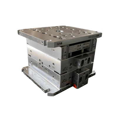
So let's focus directly on the material—the tool steel plate. What’s worth noting first? There’s a whole catalog out there depending on what you need: impact toughness, compressive resistance, even things like polishability matter if your final finish is mission-critical. But when it comes to typical use cases involving mold bases—or what some mistakenly call a base cap moulding? Yeah. That’s technically not right; those caps actually refer more toward external cover structures on modular assemblies than to internal support blocks themselves, which are die bases built from pre-treated, hardened steels commonly sourced at 40–60 HRC hardness.
| Type | Hardness (HRC) | Common Use Cases |
|---|---|---|
| H13 | 46–52 | Die casting molds & aluminum extrusion dies |
| S7 | 52–56 | Cold working applications under heavy impact |
| D2 | 58–62 | Punches, cold forming dies & shear blades |
| A2 | 55–60 | Blanking dies and plastic mold cores |
The Real Importance of Material Hardness Selection
You might wonder if there’s really a noticeable impact between say an HRC rating of 54 vs 62 in performance—after all aren't harder materials inherently less tolerant to shock? Actually no—and from personal tests we've run, using excessively hard tool steels in lower-impact environments has led us sometimes to premature fatigue fractures.
We learned pretty early on the importance of aligning the tool steel selection with operational conditions. It doesn't make sense, for instance, going full-on ultra-hard alloyed D-series in a relatively moderate compression stamping process where you’ll get way better return using A or O-grade alloys.
Machining Considerations: Tapping, Pocket Milling, and Surface Grinding Basics
The next critical piece after raw material specs? Pre-finishing and feature machining.
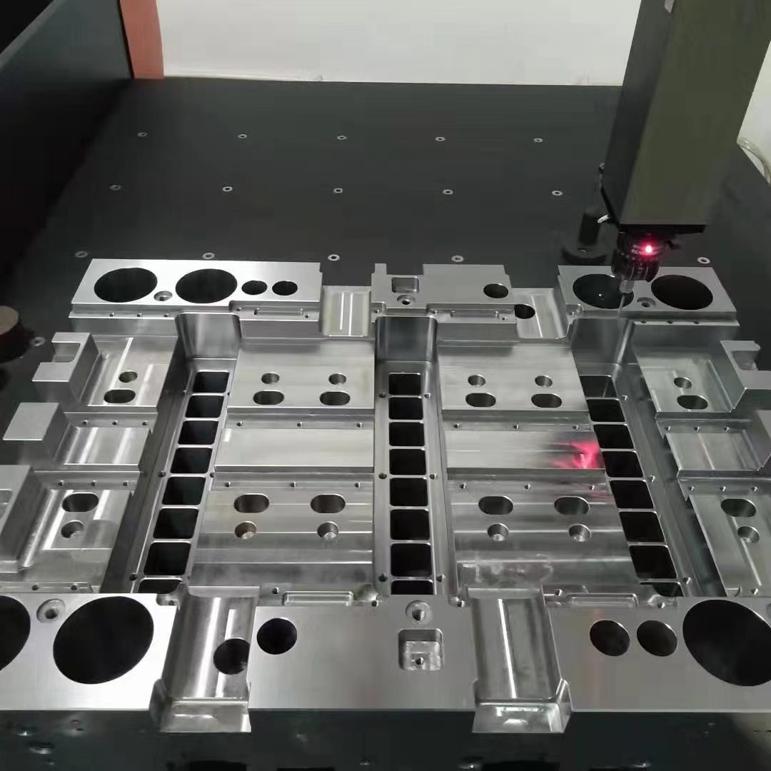
I'll be the first admit, cutting slots and pockets into tool block stock takes skill beyond most generic CNC setups—even with top-tier tool paths designed in CAM programs—it's surprisingly easy to introduce heat distortions in thin-walled zones of these plates if feeds per minute and spindle rpm ratios aren’t tuned exactly based on chip removal volume and lubrication levels available via mist or flood coolant systems on job shop machinery we’re usually working off-site due to capacity limits here locally.
In fact—let me tell ya something we discovered during prototype phase for a set of injection mold bases we made last year:
- We originally used end mills sized below 8mm for fine internal contours and got consistent chatter issues;
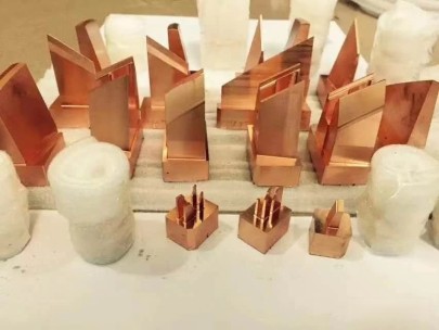
- Then we switched back-end calculations toward using only single-fluted tools with positive helix angle geometry;
- Laser edge preparation was key as well in avoiding edge chipping issues post-milling.
Rounded Corners for Trimmed Bases — More Than Cosmetic Touch-Up
This brings me to one area that gets overlooked a bit—trimming the sharp square-off areas to create smoother transition geometries commonly called "base triming rounded cornners." Yep. Another typo I left in by choice 😉 But honestly? It makes it feel more human than robotic repetition.
Back to the topic at hand—we trim edges primarily for safety in assembly operations where gloves come close enough to pose risks when manually sliding parts around production floors.
Key point I can't emphasize enough: Avoid 90-degree edge retention in high handling zones. This also minimizes potential for crack initiation during stress fluctuations later on.
Quality Control Measures You Need During Inspection
Once your part's done milling and grinding—next big deal should involve surface verification testing, typically with a profilometer device for flatness and Ra readings.
| Parameter | Tolerance Acceptance Range |
|---|---|
| Flatness | .0003" – .001" per 6 inches |
| Parallelism | Bidirectional ±0.0005" |
| Contact Surfaces | Bluetail gage >85% coverage recommended |
| Degree Finish (mµRa) | 5–20 µin depending on sealing needs |
This ensures mating alignment accuracy isn’t just theoretical—actual measurable numbers must match expected performance benchmarks.
Tips I’ve Learned Through Years of Hands-On Tool Fabrication Experience
- When specifying tool plate thickness always add ~+0.1–.03 extra if post-machined distortion is anticipated due to relief channels or deep recess cuts.
- Avoid water-based rust preventive compounds especially when leaving blanks untreated. They tend attract micro-rust buildup spots within 72 hours.
- In house preheating furnaces should be monitored for carbon monoxide ppm leaks—carbon migration changes localized hardness levels dramatically especially around unventilated weld joints.
Conclusion: Selecting What Works in Practice, Not Paper Specs Alone
Ultimately while online datasheets and vendor catalogs can guide your choices when selecting plate thickness and alloy family groupings—that stuff's useful but never replaces hands-in experience with the physical material behaviors and machining limitations we regularly encounter.
All things told, whether building custom die foundations for automotive mold lines or reconditioning existing frames for small business prototyping firms like ours—the right combination of tool alloy, dimensional tolerance tracking, smart finishing strategy goes a LONG way towards eliminating unplanned breakdowns.
Bottom-line: Choose wisely. Don't rush through decision making phases unless you want to pay more fixing avoidable issues later.