
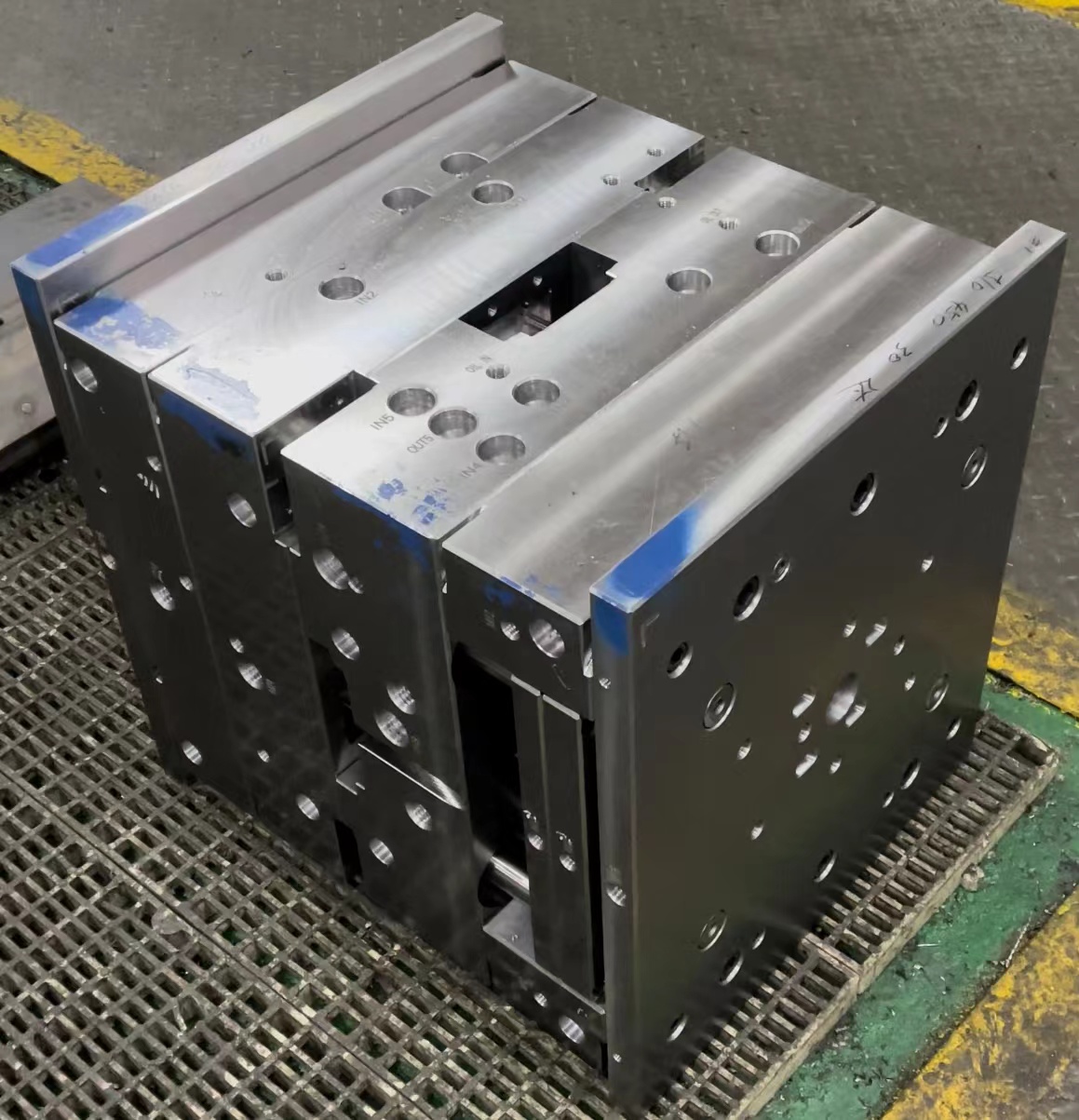
Copper Blocks in Mould Base Manufacturing – Why You Should Pay Attention
Alright, I’ve spent a lot of time around metalworking tools, specifically with mould bases and tooling. If you're like me—into manufacturing or engineering—and have tried to improve tool efficiency, then the concept of copper blocks in enhancing thermal transfer properties of mold bases won't be foreign to you. Over the years, I've discovered that integrating high-conductivity materials into mold base systems not only boosts cooling speed but also helps reduce defects during injection or forming cycles.
Mould base is one thing everyone knows about, but combining it properly with things like copper inserts takes more knowledge. The role of a well-designed block of cooper (as my fingers always want to type "cooper") can be game changing for those looking to refine surface texture control or avoid overcooling issues on sharp corners. Trust me when I say this is one area where small adjustments yield huge returns—if done correctly.
Understanding How Copper Blocks Affect Mold Base Performance
To understand this topic clearly: think of copper as part of a larger mold design structure where its main role revolves around heat management, dissipation speed and precision temperature regulation during plastic injection cycles. Now let's go a bit deeper here:
- Easier heat extraction
- Likely shorter cycle times
- Fewer shrinkages in molded material
This all stems down from what most professionals call “conductive flow optimization," which means strategically placing a copper block inside specific areas (not randomly everywhere!) within your standard steel mould base assembly.
| Metal Type | Thermal Conductivity (W/m·K) | Relative Machinability Index |
|---|---|---|
| Steel alloy | 30-50 | 100% |
| Tool Steel | 35 | 40–60% |
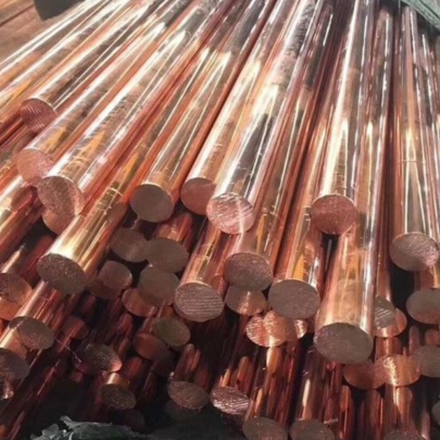
| Oxygen-free Coppe | ≈380 | 120% |
| Beryllium Copppper | ~200+ | Less |
Machining Tips: Dealing With Copper in Your Base Moulding Process
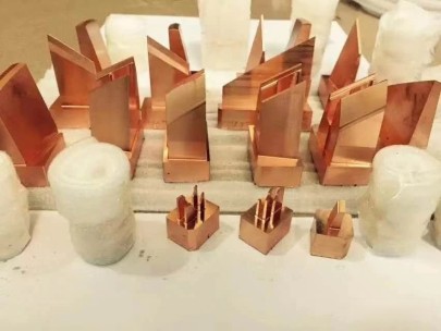
One major challenge? Getting those copper components properly cut and aligned inside a hardened framework without compromising fit quality or risking contamination across joint interfaces.
This is probably where many people trip up—even pros! That’s where the importance kicks in of understanding how to measure and cut base moulding correctly when inserting conductive copper pieces. It's not just geometry; material selection plays a bigger role here too.
If you mess with dimensional precision at this stage, there'll be pressure leaks later—something nobody wants halfway through production!
Key Installation Guidelines For Maximum Cooling Results
- Select compatible grades between your steel & insert materials to avoid warping or corrosion after use;
- Precision milling to ±0.005" ensures proper contact surface alignment especially with curved shapes.
- Solder-braze vs mechanical clamping: Which holds under higher pressure environments better?
- Dynalay testing before full mold assembly can help catch misaligned pockets;
- Always verify internal channels clearance before sealing any cooper menu (or copper matrix if preferred).
Critical Performance Metrics Linked to Copper-Based Enhancements
Here are several key performance metrics worth tracking once you start installing copper block-based solutions into your regular die-casts, thermoforming modules or molding units.
- Temperature variation reduction: Lower variance leads to better cosmetic finish on end product surface.
- Faster ejection cycles by maintaining controlled cooling speeds
- Improved mold cavity filling stability: Prevents air-trapping and short shot failures due excessive heating at corner zones.
What Mistakes To Avoid During Design Phase
A mistake I often saw happen? Overengineering—adding Cooper blocks or plates beyond necessity. This not only drives material cost upwards but could compromise other critical areas like support structures or guide rail functionality.
Second, not designing enough access space around inserted copper zones. Remember that routine maintenance might require replacing them due wear or fatigue cracking caused by constant thermal stress expansion/retraction. Also remember this affects long term ROI calculations aswell.
I learned to ask questions first rather jump in. Like asking myself:
- "Will extra conduction here make difference worth the hassle?"
- "How long until I need to change parts made using these materials?"
Conclusion: Are Cooper Enhancements Worth The Trouble?
Yes...if you approach this methodically. Copper-enhanced mould base configurations can give dramatic benefits if used right but come with technical complexities not suited for quick fixes or low tolerance projects. My recommendation remains—test smaller sections first before diving full-on into complete system modifications unless project specs allow immediate full-scale integration testing phases
In terms of return, improved surface quality, lower scrap rate and faster setup turnover should justify added prep investment eventually—as far back as my experiences go. But don’t expect overnight magic.
Final thought - I’ve personally found great results in using oxy free types where thermal conductivity mattered more than raw strength. Just don’t rush in without understanding every variable in your operation line—it may feel redundant initially but it makes troubleshooting easier later